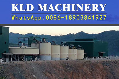
Selection and calculation of leaching tanks
2020-10-09 10:28Introduction:Selection and calculation of leaching tank s The factors such as mine size, grinding fineness, ore specific gravity, slurry concentration, power consumption and operation and maintenance should be considered in selecting leaching grooves.
The factors such as mine size, grinding fineness, ore specific gravity, slurry concentration, power consumption and operation and maintenance should be considered in selecting leaching grooves. At present, the use of double impellers low-speed energy-saving immersion slot. Table 7.1-1 shows the technical performance of domestic SJ double impeller low speed energy saving agitator.

|
specifications Diameter × height /mm×mm |
available capacity/m3 | impeller diameter /mm | Impeller speed/r·min-1 | power of motor /kw | weight of equipment/kg |
|
¢2000×2500 ¢2500×3150 ¢3150×3550 ¢3550×4000 ¢4000×4500 ¢4500×500 ¢5000×5600 |
6 13 24 34 48 72 98 |
740 925 1160 1320 1550 1750 1900 |
73 57 47 41 36 31 28 |
1.5 2.2 3.0 4.0 5.5 7.5 7.5 |
2800 3371 5628 6646 8285 10803 14430 |
According to the known conditions above, the total volume of the leaching tank needed to guarantee the leaching time can be calculated, then the specifications of the leaching slot can be selected, and the number of the leaching tanks can be calculated finally.
The total volume of the leaching tank is calculated by the following formula:
V=Q*(1/δ+R)*t/(24*φ)
In the form V——total volume of leaching tank;
Q——daily ore-treatment amount t / d;
δ——ore gravity,t/m3;
R——slurry liquid to solid ratio;
t——Required leaching time (determined by test),hours
φ——The coefficient of volume utilization of leaching tanks is shown in Table 7.1-2.
Table 7.1-2 volumetric utilization coefficient of leaching tanks φ
| Leaching tank specification | Leaching of gold concentrate from flotation | All slimecyanidation |
remarks |
|
¢≤2500 ¢=3000 ¢≥3500 |
0.8~0.83 0.83~0.86 0.86~0.88 |
≤0.92 0.92~0.93 0.93-0.95 |
The lower limit should be taken when gold concentrate oars are floatation foam products |
The number of tanks for leaching is calculated according to the following formula
n=V/V0
In the form n——Number of tanks required for leaching;
V——Total volume of leaching tanks,m3;
V0——Single effective volume of selected leaching tank,m3;
Selection of aeration volume and pressure fan in dip tanks:
The total air volume is calculated according to the maximum quota and the wind pressure, and the type and the number of the compressor are selected according to the total air volume. At best, the leaching tanks and wind pressure are listed in Table 7.1-3.
Table 7.1-3 Air volume and wind pressure of leaching tanks
|
Leaching tank form |
aeration volume |
Calculated pressure /kPa |
|
| tanks surface area/m3(m2·min)-1 | tanks volume/m3(m3.min)-1 | ||
|
Mechanical agitating tank Air agitating tank Double impeller hollow shaft air inlet agitating tank |
0.1~0.2 0.15~0.2 |
0.013~0.025 0.02 |
|

