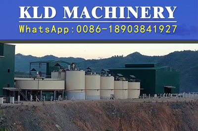
The main equipment of the adsorption circuit of the carbon p
2020-09-16 09:07Introduction:The main equipment of the adsorption circuit of the carbon p ropeller-the adsorption t ank of the carbon p ropeller The equipment of the adsorption circuit of the propeller should meet the following requirements: (1) making the pulp in the
The equipment of the adsorption circuit of the propeller should meet the following requirements: (1) making the pulp in the adsorption tank fully contact with the activated carbon; (2) the screen between the tanks can effectively separate the pulp from the activated carbon; (3) the wear of the carbon in the loop is as small as possible; (4) to avoid the short-circuit phenomenon of slurry in the adsorption tank as far as possible. The main equipment of the adsorption loop of carbon propeller is the adsorption tank of carbon propeller, the screen between tanks and the activated carbon conveying device.

The axial-flow agitator which will be used in alumina production has been successfully used in the propeller process after revamping in recent years. Axial flow mixing tank has air mixing and mechanical mixing two types. The structure of the axial flow mechanical agitator is shown in Fig. 5-31. There is an inflatable circulating tube in the center of the slot, and the top of the circulation pipe is equipped with a hydrofoil impeller of the lower pump. When rotating, the slurry flows downward through the circulating pipe, so that the pulp can be effectively circulated. Because the impeller is axial flow and the impeller section is curved, the impeller tip velocity is small, the axial flow velocity is large, the radial velocity is small, and the shear force is small. There are many vertical grooves in the lower part of the central circulating pipe, which extends from the bottom to the highest point of the sedimentary slurry, which is favorable to the equipment starting after a long period of shutdown, and can make the pulp circulate and gradually promote the slurry to be suspended. But slotting may short-circuit the slurry. The difference between axial-flow mechanical stirred tank and other mechanical agitator is that the tank must be filled with slurry before it can start running, the ratio of height to diameter can reach 2: 1. The experience of the Pingsen Plant in the United States shows that, as long as the diameter of the aerated circulating tube is properly selected, its energy consumption is only 30% of that of the ordinary mechanical stirring tank, and the ore particles are suspended evenly, the activated carbon is less worn and the gold recovery rate is high, thus solving the oil pollution. The problems of high amount of cyanide and sand deposition during blackout are expected to become the main equipment of the propeller plant.
The research direction of the adsorption tank for carbon propeller is to improve the structure of the open mechanical stirring tank and to study the new impeller in order to achieve good stirring, reduce the shear force, increase the elevating height and enhance the aeration, at the same time, it can prevent the short circuit of the slurry and reduce the energy consumption.
At present, XFCAG ,XQC series adsorption leaching grooves are mainly used in China, which are mixed by mechanical and air agitation. The speed of impeller is generally 45 round/ min, and the blowing pressure of main shaft is 196.2 kPa. Uniform stirring, small carbon wear, low power consumption.

